
Learn how to install your Mount Up! Horizontal Gun Mounting System:
PDF Instructions
Tools required for installation:
- Stud Finder (or other method)
- Electric Drill
- Bubble Level
- 3/16″ Drill Bit
- 7/16″ Socket with Ratchet
- 3/16″ Allen Key or Hex Driver
- 5/32″ Allen Key or Hex Driver
- Small Hammer or Mallet
- 1/8″ Pin Punch (if available)
- 5/64″ Allen Key or Hex Driver
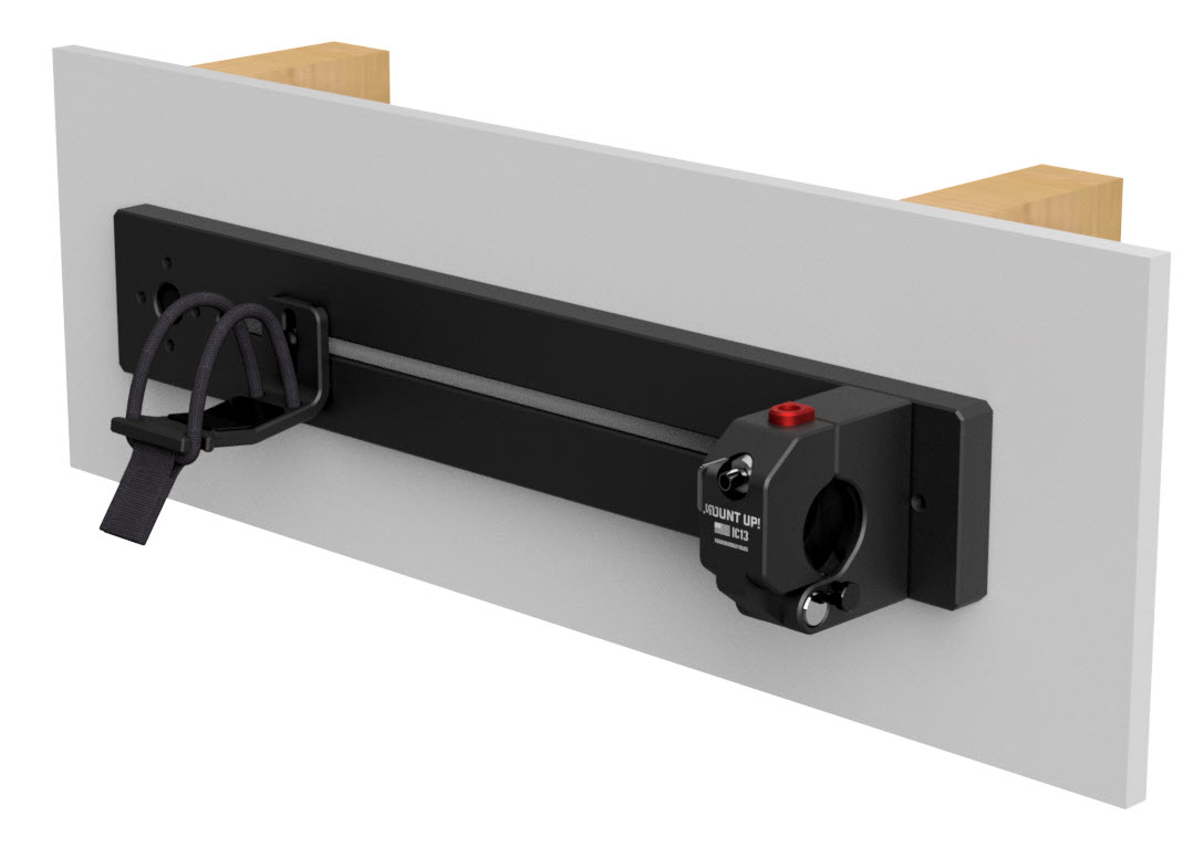
- Unpack the contents of your package and remove the red clevis pin retaining sticker on the right-hand side of your clamping bracket assembly (#20). Break your clamping bracket assembly down into three pieces for installation (front assembly, clevis pin, and rear block).
- Locate the wood studs where you want to mount your bracket. Brackets can also be installed into block or concrete walls with appropriate anchors (not included).
- ***IMPORTANT*** The main clamp of the system should cover ONE of the mounting holes in the plate (#1) (either left or right, depending on your preference). The lag bolt (#4) will not be accessible after the system is assembled. We also recommend covering the other hole with the handguard rest (#2) if possible. This will depend on your weapon configuration (see step #19 below).
- Choose which side of the system your clamp assembly will be on, either left or right, and mark this hole location of the mounting plate (#1) on the wall.
- Drill a 3/16″ pilot hole at this location, into the stud.
- Screw the lag bolt (#3) with washer (#4) into the stud using a 7/16″ socket and ratchet. Do not tighten.
- Place your bubble level against one of the long sides of the mounting plate (#1) and mark the location for the second hole.
- Drill a 3/16″ pilot hole at this location, into the stud.
- Repeat step 6 at the second location.
- Ensure that your rail is level and tighten the lag bolts.
- Cover the lag bolt heads with black hex covers (#5).
- Choose the four “bumpers” (#’s 10, 16, 17) that you need for your firearm using the guide below. Press them into the grooves on the inside of the rear block of the clamping bracket assembly, and the front block assembly.
- Using a 3/16″ allen key or driver, mount the rear block to the rail (#1) using the allen cap screws (#11).
- Align the holes in the rear block and the front block assembly, and insert the clevis pin to join the parts. THE HOLE IN THE CLEVIS PIN MUST BE ALIGNED WITH THE HOLE IN THE REAR BLOCK.
- Use a small hammer or mallet to pin the clevis pin in place, using the 1/8″ spring pin (#12). Use a pin punch (if available) or the second included spring pin (#12) to tap the spring pin slightly past flush to lock the clevis pin in place.
- Screw the nylon thumb screw (#14) into place on side of the rear block which the buttstock of the weapon will be. The angle on your buffer tube will rest against this post, preventing any damage to your weapon or bracket while in use.
- Peel the backing off the handguard pad (#8) and stick it to the handguard rest (#2), centered in the“V” groove.
- Using the 5/32″ allen key or hex driver and 1/2″ black button head screw (#5), fasten the handguard rest (#2) to the mounting plate (#1) at the desired location over top of the lag bolt (#3).
- IF FASTENING HANDGUARD REST IN SLOT – Use the t-nut (#19) to fasten the handguard rest (#2) to the mounting rail (#1) in the SLOT. This works exactly like an M-LOK rail system. Look into the slot and make sure that the t-nut is properly engaged in the slot in the rail. The t-nut should be vertical, not at an angle or horizontal. VISUALLY INSPECT THE T-NUT FOR PROPER ALIGNMENT AND PULL ON THE HANDGUARD REST TO ENSURE IT IS PROPERLY FASTENED.
- Unlock your bracket with the key (#16). Open the bracket by depressing the red button and place your firearm into the bracket. Close the bracket and ensure that the red release button has engaged. The bracket clamps on the buffer tube between the castle nut, and the angled portion of the tube.
- TO LOCK YOUR BRACKET, REMOVE THE KEY (#16, IF PRESENT), AND PRESS THE PLUNGER INTO THE LOCK. DOUBLE CHECK THAT THE PLUNGER REMAINS IN POSITION, AND CHECK FOR PROPER LOCK BY ATTEMPTING THE DEPRESS THE RED BUTTON.